A power semiconductor datasheet may show several different values for the same parameter. A table can include minimum, typical and maximum figures, while its heading, final column or footnotes define the conditions under which those figures were obtained. These values are not interchangeable.
Correct interpretation requires more than finding the highest voltage or current rating. The reader must determine whether a value is a limiting rating, a guaranteed characteristic or a typical measurement, then review the associated temperature, drive conditions and test method. This article provides a practical, manufacturer-neutral approach to reading these distinctions.
Quick answer: always read the complete parameter row
No numerical value in a power semiconductor datasheet should be separated from its parameter name, symbol, qualification, unit and test conditions. A value such as 1200 V, 450 A or 1.8 V does not reveal by itself whether it is a continuous operating value, a pulsed limit or a typical result obtained at one measurement point.
The first step is therefore not to find the largest number, but to understand the structure of the document. Maximum ratings, operating ranges, electrical characteristics, thermal data, diagrams and test circuits serve different purposes.
A maximum rating is a limit, not a design target
A maximum rating, absolute maximum rating or maximum rated value normally defines a boundary that must not be exceeded. It does not mean that the component should be operated continuously at that value. The rating does not automatically include the voltage, current, temperature or lifetime margin required by the application.
It is particularly important to establish whether a maximum current is continuous or pulsed. A pulsed rating is normally linked to pulse duration, duty cycle, case or junction temperature and drive conditions. Without these conditions, a pulsed maximum must not be treated as continuous current capability.
For voltage ratings, the reader should also distinguish between repetitive and non-repetitive peak values. They describe different stress conditions even where their numerical values happen to be identical.

Minimum, maximum and typical characteristics
Electrical-characteristics tables often contain minimum, typical and maximum columns. Each column has a different role.
| Data category | What does it express? | How should it be used? | Main risk |
|---|---|---|---|
| Maximum rating | An upper boundary beyond which damage or reliability degradation may occur | As a limit with an appropriate application margin | Treating it as a recommended operating point |
| Guaranteed maximum | An electrical characteristic specified with an upper limit under stated conditions | For worst-case assessment | Ignoring the specified conditions |
| Guaranteed minimum | A lower limit specified under stated conditions | For checking minimum performance or operating boundaries | Replacing it with a typical value |
| Typical value | A representative measurement under reference conditions | For estimates, comparisons and preliminary loss assessment | Treating it as a guaranteed tolerance limit |
| Characteristic curve | Parameter behaviour as a function of temperature, current, voltage or another variable | For understanding trends and relationships | Reading it as an exact production limit |
A typical value is a useful reference, but it does not normally prove that every manufactured device will produce the same result. If system safety depends on an upper or lower boundary, look for a guaranteed minimum or maximum value and any additional design guidance supplied by the manufacturer.
The test condition is part of the value
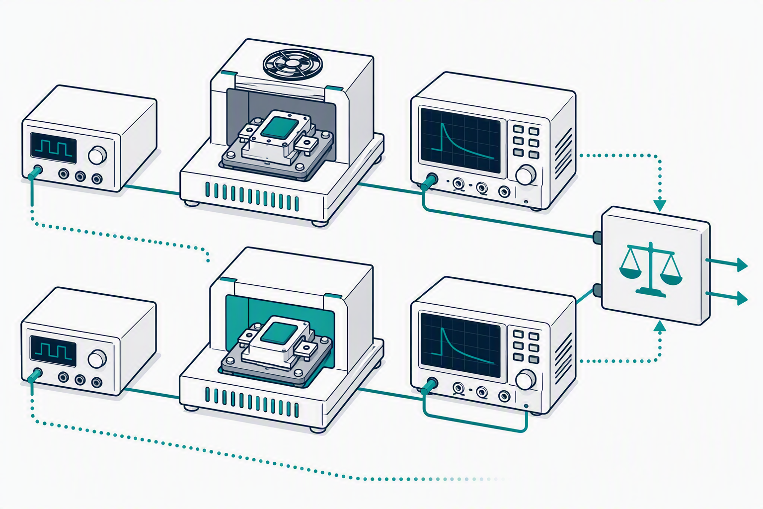
The test-condition or notes column is not supplementary decoration. It defines the measurement point at which the value applies. Turn-on energy, for example, may depend on collector current, DC-link voltage, gate voltage, external gate resistance, junction temperature and stray inductance in the test circuit.
Two figures are directly comparable only when the essential measurement conditions match or when the manufacturer provides suitable correction curves. Matching parameter names alone do not guarantee valid comparability.
- Check whether the temperature is junction, case or ambient temperature.
- Review the current, voltage and drive conditions.
- Identify pulse duration, frequency and duty cycle.
- Read the footnotes and the reference to the test circuit.
- Confirm whether the value is typical or a guaranteed limit.
Temperature is not a secondary condition
The electrical behaviour of a power semiconductor can depend strongly on junction temperature. Ambient temperature, case temperature and the internal semiconductor junction temperature must therefore be distinguished.
If a current rating is specified at a low case temperature, it can only be interpreted correctly when the application cooling arrangement can maintain a comparable condition. Maximum junction temperature is also an upper limit rather than a recommended continuous control target.
When reading thermal resistance, identify whether the value applies from junction to case, junction to ambient or across another thermal path. For power modules, the interface material, cooler surface, mounting arrangement and cooling system introduce additional application-specific conditions.
Curves explain relationships but do not replace limits
Characteristic diagrams help explain how conduction voltage, switching energy, gate charge or thermal impedance changes with load and temperature. These plots are commonly typical curves and should not automatically be treated as guaranteed production boundaries.
Begin by identifying both axes and their scales. Some diagrams use logarithmic scaling. Then check the temperature, drive condition and pulse range associated with the curve. Finally, return to the tabulated ratings and confirm that the selected point does not violate another limit.
Preliminary, target and final documents
The status of the document matters as much as the qualification of the individual parameter. A target value may express a development objective. A preliminary datasheet may contain specifications that are still subject to revision, while a final document represents a more mature released specification. The exact meaning must be interpreted according to the document-control terminology of the manufacturer.
Before purchasing a component or assessing a possible alternative, verify the datasheet version, release date and revision history. Older and newer documents for the same part number may contain revised values, conditions or explanatory notes.
A safe order for comparing datasheets
Start by identifying the device technology, voltage class, current rating, package and internal topology. Then review thermal constraints, static characteristics, dynamic characteristics, drive requirements and mechanical data.
Similar voltage and current ratings, or a visually similar package, do not prove compatibility. Internal topology, gate-drive requirements, dynamic behaviour, insulation, terminal arrangement, mounting, thermal paths and short-circuit characteristics may all differ.
Important: Selecting the appropriate component always requires technical verification against the specific application and operating conditions.
Summary
Reading a power semiconductor datasheet correctly does not begin with finding the highest voltage or current. First determine whether the value is a maximum rating, a guaranteed minimum or maximum, or a typical characteristic. Then review the complete test condition, including temperature, drive parameters, pulse duration and relevant footnotes.
Characteristic curves help explain trends but do not necessarily provide guaranteed boundaries. Two components can only be compared under matching or appropriately normalised conditions. Final component selection always requires application-specific technical verification.
Frequently asked questions
Is a typical value guaranteed?
Normally not. A typical value represents characteristic behaviour under stated reference conditions. Where system safety depends on an upper or lower boundary, use the guaranteed minimum or maximum specification.
Can a device operate continuously at its maximum rating?
A maximum rating is a limit, not automatically a recommended working point. Application margin, transient stress, temperature and lifetime requirements must be assessed separately.
Why can the same parameter have different values in two datasheets?
The temperature, measurement current, voltage, gate drive, pulse duration, test circuit or parameter qualification may be different. The figures can only be compared after reviewing the complete conditions.
Is a value read from a characteristic curve guaranteed?
Only when the manufacturer explicitly defines the curve as guaranteed. Characteristic diagrams generally show typical behaviour and relationships.
Are voltage, current and package sufficient for selecting a replacement?
No. Topology, gate drive, dynamic parameters, thermal characteristics, insulation, terminal arrangement and mechanical construction must also be reviewed.
Have a question? Contact our team!
Choosing the right power semiconductor requires considering not only the datasheet specifications, but also the real-world operating conditions of the application. If you need assistance with a specific component or technical requirement, our team is ready to help.
Sources
Infineon Technologies: Industrial IGBT Modules – Explanation of Technical Information, AN 2011-05, V1.2.
Infineon Technologies: Datasheet Explanation Update for Automotive MOSFETs.
Hitachi Energy: 5SDD57X6500 Rectifier Diode datasheet, maximum rated values, characteristic values and test conditions.
Hitachi Energy: Semiconductors official product and technology page.